Write nodes to control the rover robot’s actuators based on sensor data. In this scenario, let’s assume the rover is supposed to follow a line using an IR sensor. Here’s a simplistic example using Python and ROS:
#!/usr/bin/env python

import rospy
from std_msgs.msg import String
from std_msgs.msg import Float64

def ir_callback(data):
    # Assuming data.data contains the IR sensor reading
    ir_reading = data.data
    command = Float64()

    if ir_reading < 0.5:  # Assuming 0.5 is the threshold for line detection
        # Turn left if line is to the left
        command.data = -0.5
    elif ir_reading > 0.5:
        # Turn right if line is to the right
        command.data = 0.5
    else:
        # Go straight if on the line
        command.data = 0.0

    # Publish the command to the rover's actuator
    pub.publish(command)

if __name__ == '__main__':
    rospy.init_node('rover_control', anonymous=True)
    pub = rospy.Publisher('actuator_command', Float64, queue_size=10)
    rospy.Subscriber('ir_sensor_data', String, ir_callback)
    rospy.spin()
Now write the sensor driver node file. The specifics of how to interact with your hardware depend on the type of sensor and the interface it uses (e.g., I2C, SPI, USB, etc.). In this example, let’s assume you have an IR sensor that communicates via a serial interface and outputs distance values as simple text strings.
#!/usr/bin/env python

import rospy
import serial
from std_msgs.msg import String

def read_sensor_data(ser):
    # Assuming the sensor sends data as a string terminated by a newline
    data = ser.readline().strip()
    return data

if __name__ == '__main__':
    rospy.init_node('ir_sensor_driver', anonymous=True)
    pub = rospy.Publisher('ir_sensor_data', String, queue_size=10)

    # Assuming the sensor is connected to /dev/ttyUSB0 at 9600 baud
    ser = serial.Serial('/dev/ttyUSB0', 9600)

    rate = rospy.Rate(10)  # 10hz

    while not rospy.is_shutdown():
        sensor_data = read_sensor_data(ser)
        rospy.loginfo(sensor_data)
        pub.publish(sensor_data)
        rate.sleep()

    # Close the serial connection
    ser.close()
Further, Below is a simplified example of what the ROS node for ball chasing might look like in Python, using ROS and OpenCV
#!/usr/bin/env python

import rospy
import cv2
import numpy as np
from cv_bridge import CvBridge
from sensor_msgs.msg import Image
from std_msgs.msg import Float64

def image_callback(img_msg):
    bridge = CvBridge()
    cv_image = bridge.imgmsg_to_cv2(img_msg, "bgr8")

    # Assuming the ball is red
    lower_red = np.array([0, 120, 70])
    upper_red = np.array([10, 255, 255])

    hsv = cv2.cvtColor(cv_image, cv2.COLOR_BGR2HSV)
    mask = cv2.inRange(hsv, lower_red, upper_red)

    contours, _ = cv2.findContours(mask, cv2.RETR_TREE, cv2.CHAIN_APPROX_SIMPLE)

    if contours:
        largest_contour = max(contours, key=cv2.contourArea)
        (x, y), radius = cv2.minEnclosingCircle(largest_contour)
        center = (int(x), int(y))
        radius = int(radius)

        if radius > 10:  # adjust threshold as necessary
            # Compute error between center of image and center of ball
            error = center[0] - cv_image.shape[1]/2
            pub.publish(error)

if __name__ == '__main__':
    rospy.init_node('ball_chaser', anonymous=True)
    pub = rospy.Publisher('steering_command', Float64, queue_size=10)
    rospy.Subscriber('camera_image', Image, image_callback)
    rospy.spin()
Next, dive deep to understand how TF is used for complex movement such as a robot arm:
#!/usr/bin/env python

import rospy
from std_msgs.msg import Float64
import numpy as np

# Function to compute joint angles based on a circular path
def compute_joint_angles(t):
    # Parameters for the circular path
    radius = 0.1  # meters
    center = [0.5, 0.5]  # x, y coordinates of the center of the circle

    # Compute the desired end-effector position
    x = center[0] + radius * np.cos(t)
    y = center[1] + radius * np.sin(t)

    # Simplified inverse kinematics calculations
    # These equations are made up for this example and will not work for a real robot
    joint1_angle = np.arctan2(y, x)
    joint2_angle = np.arcsin(radius / np.sqrt(x**2 + y**2))
    joint3_angle = np.arcsin((y - np.sin(joint1_angle + joint2_angle)) / radius)

    return joint1_angle, joint2_angle, joint3_angle

def control_arm():
    rospy.init_node('arm_control', anonymous=True)

    joint1_pub = rospy.Publisher('/robot/joint1_position_controller
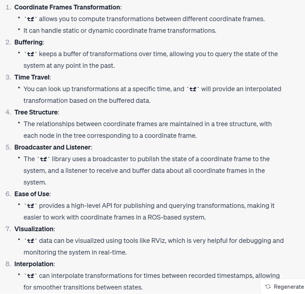
The tf (transform) library in ROS (Robot Operating System) is crucial for managing multiple coordinate frames over time. It maintains the relationship between coordinate frames in a tree structure buffered in time and lets you transform points, vectors, etc between any two coordinate frames at any desired point in time. Here are some key aspects and functionalities of the tf library: